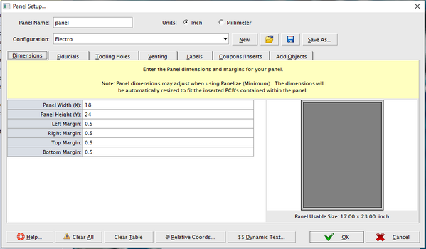
The PANEL array is used to create and build a complete panel. It can automatically panelize/merge jobs, create fiducials, tooling holes, perform venting, and more. Jobs must be imported and available before Panel. PANEL array is optional. Relative Coordinates are also supported.
Fields in the PANEL array
| Description |
| NAME | The name of the panel. This will be the name used when it creates the panel. |
| UNITS=VALUE | Units to use for this panel array. Must be either: INCH or MM (Default: MM)
|
| WIDTH=VALUE | Panel Width. The value is defined in the panel units. |
| HEIGHT=VALUE | Panel Height. The value is defined in the panel units. |
| BORDERSPACING | Defines the panel margins between edge of panel and inserted PCB's. Border spacing is defined as either:
BORDERSPACING=LEFT,RIGHT,TOP,BOTTOM
or if all spacing is the same for all sides use one value.
BORDERSPACING=MARGIN
|
| STEPREPEAT | This field contains the Job Name, X and Y Origin, X and Y Spacing, X and Y Count, Job Angle (must be 0, 90, 180, 270), Mirror (must be either: YES or NO), and the optional Job Orientation to use (Lower-Left, Center, Origin) all separated by a commas.
- Note
- Origin and Spacing values are defined in the panel units.
Note: If you only require a 1 up (no array) use INSERT (see below).
Note: By default use the Lower-Left of each Job as the insert point. If you wish to use the Insert Point to be the Job Center use Center. If you wish to insert by the actual 0,0 origin of the Job use Origin.
STEPREPEAT=JOB,X,Y,JOB_SPACING_X,JOB_SPACING_Y,COUNT_X,COUNT_Y,ANGLE,MIRROR,ORIGIN
JOB: Name of job (ie. child cell) which is to be inserted. Cannot be the same name as the panel (ie. parent cell). Dynamic Job References are also supported.
X, Y The StepRepeat Insert coordinate.
JOB_SPACING_X Job Spacing (Horizontal)
JOB_SPACING_Y Job Spacing (Vertical)
COUNT_X Job Count (Horizontal)
COUNT_Y Job Count (Vertical)
ANGLE The insert angle.
MIRROR Assign TRUE for mirrored insert and FALSE for non-mirror. YES or NO is also accepted
ORIGIN Optional. Job Orientation to use: LOWER-LEFT, CENTER, ORIGIN By default use the Lower-Left of each Job as the insert point. If you wish to use the Insert Point to be the Job Center use Center. If you wish to insert by the actual 0,0 origin of the Job use Origin.
Example: STEPREPEAT=board1,17.0,4,3.8,3.4,2,5,90,No,Origin
|
| INSERT | Add an insert to the Panel. Relative Coordinates are also supported.
- Note
- If you only require an array use STEPREPEAT above.
INSERT=JOB,X,Y,ANGLE,MIRROR,[ORIGIN]
JOB name of job (ie. child cell) which is to be inserted. Cannot be the same name as the panel (ie. parent cell). Dynamic Job References are also supported.
X, Y are the Insert coordinate.
ANGLE is the insert angle.
MIRROR assign TRUE for mirrored insert and FALSE for non-mirror. YES or NO is also accepted
ORIGIN is optional Job Orientation to use (Lower-Left, Center, Origin). By default use the Lower-Left of each Job as the insert point. If you wish to use the Insert Point to be the Job Center use Center. If you wish to insert by the actual 0,0 origin of the Job use Origin.
Example:
INSERT=Board4,17.5,15.35,180,No
INSERT=Board4,17.5,15.35,180,Yes
INSERT=pcb,100,100,0,No,Center
|
| FIDUCIAL | Add Fiducials to the Panel. Define Fiducial Shape, Width, Mask Shape, Mask Width, X/Y Coordinates, Fiducial Type, and layer(s). Relative Coordinates are also supported.
FIDUCIAL=shape,width,mask_shape,mask_width,x,y,fid_type,layer(s)
shape=[circle hash target cross octagon butterfly donut rectangle diamond]
mask_shape=[circle square]
fid_type=[local global panel]. If none, may be left intentionally blank
For additional information view, https://support.numericalinnovations.com/support/discussions/topics/14000018616
Example:
FIDUCIAL=circle,1,rectangle,2,@left+5,@bottom+7.2,Panel,[Top+Bottom]
FIDUCIAL=rectangle,1,rectangle,2,@right-25,@top-5,,topside34dd,botside34dd
|
| TEXTLABEL | Add Text Label to the active Panel. Relative Coordinates are also supported.
TEXTLABEL=font,height,x,y,rotate,mirror,negative,alignment,layer(s),text_label
font=Choose the font style you wish for the Text label. If empty "fab.fnt" will be used. For more information about font style view, Font File Reference
mirror=[no yes] If yes, mirrored Horizontally (about the Y axis). If empty will be "no" mirror.
negative=[no yes] If yes, text will be clear. Make sure text is over an existing metal area or else it will appear invisible. If empty will be "no" (positive)
alignment=VALUE Assign the alignment for TEXT. Choose from: upperLeft or UL, centerLeft or CL, lowerLeft or LL, upperCenter or UC, centerCenter or CC, lowerCenter or LC, upperRight or UR, centerRight or CR, lowerRight LR. (default: LL) text_label=Enter the text you require on the panel. All dynamic Text is fully supported, https://support.numericalinnovations.com/support/discussions/topics/14000018603
For additional information view, https://support.numericalinnovations.com/discussions/topics/14000018617
Example:
TEXTLABEL=arial,2,@right-15,@bottom+5,0.0,1,0,LL,[Bottom_Silk],PANEL LABEL
TEXTLABEL=arial,2,@left+15,@bottom+5,0.0,0,0,LC,[Top_Silk],PANEL LABEL
TEXTLABEL=,1.6,@right-100,@top-6.5,0.0,1,0,LL,[Bottom_Silk],dX: $$PANEL_SPACING_X
TEXTLABEL=,1.6,@left+2,@top-4,0.0,0,0,UL,[Top_Silk],TOP SIDE LEFT CORNER. PCB#$$WORKSPACE_NAME x $$PANEL_TOTAL
TEXTLABEL=fab,1.6,@left+2,@top-9,0.0,0,0,CC,[Top_Silk],PANEL ORIGIN BOTTOM LEFT OF PCB AREA
TEXTLABEL=,1.6,@left+2,@top-6.5,0.0,0,0,LL,[Top_Silk],$$PANEL_WIDTH x $$PANEL_HEIGHT x $$PANEL_THICKNESS
|
| TOOLINGHOLE | Add NC Tooling Holes and then enter Width, Height, X/Y Coordinates, Rotation, and Clearance. Relative Coordinates are also supported.
TOOLINGHOLE=shape,width,height,x,y,rotation,clearance
shape=[drill slot]
For additional information view, https://support.numericalinnovations.com/discussions/topics/14000018619
Example:
TOOLINGHOLE=drill,2,2,5,7.2,0,1
TOOLINGHOLE=slot,4,1,@right-25,@top-5,0,1
|
| COUPON | Insert Coupons and other external resources into the Panel. Relative Coordinates are also supported.
COUPON=resource,x,y,rotate,mirror,clearance,layer(s)
resource=Resources include: Job files (.job), PCB Matrix Files (*.xml,.fm6), and existing Job/Panels (already loaded and available).
For additional information view, https://support.numericalinnovations.com/discussions/topics/14000018618
Example:
COUPON="C:/Support/Coupon32.job",@l+100,+10,0,No,1
COUPON="C:/Support/customfeature.fm6",34.5,75,0,No,1,[Top+Bottom]
COUPON=myjobname,200,5,0,No,1,[Top+Bottom]
|
| VENT | Venting adds copper which isn't connected to any nets on the board and does not affect the functionality. The are various purposes for Venting (i.e Thieving) such as improving etching throughout the entire panel, to improve manufacturing efficiency, and more. Typically small copper circles, squares or even a solid copper plane will be added to larger blank spaces to even out the copper distribution across a copper layer. Relative Coordinates are also supported.
VENT=rail,panel_clearance,job_clearance,symbol_clearance,width,layer(s)
VENT=vrail,panel_clearance,job_clearance,symbol_clearance,width,layer(s)
VENT=hrail,panel_clearance,job_clearance,symbol_clearance,width,layer(s)
VENT=solid,panel_clearance,job_clearance,job_clearance,symbol_clearance,layer(s)
VENT=dot,panel_clearance,job_clearance,symbol_clearance,patternX,patternY,dy,shape1,width1,x1,dx1,shape2,width2,x2,dx2,layer(s)
VENT=hatch,panel_clearance,job_clearance,symbol_clearance,patternX,patternY,width1,offset1,angle1,width2,offset2,angle2,width3,offset3,angle3,layer(s)
For additional information view, https://support.numericalinnovations.com/discussions/topics/14000018620
Example:
VENT=solid,0.1,0,0.1,[Top+Bottom]
VENT=dot,0,0.1,0.1,0,0,0.12,circle,0.06,0,0.12,circle,0.06,0.06,.12,[odd metal]
VENT=hatch,0.1,0,0,0,0,0.01,0.5,0,0.01,0.5,45,0.01,0.5,90,[even metal]
|
| OBJECT | Add various Objects into the Panel such as Rout, Score, Polygon, Line, Path, Circle, Arc. Relative Coordinates are also supported.
OBJECT=SHAPE,LAYER,COMPOSITE,SHAPE_DESCRIPTION
LAYER name. Dynamic Layer Types are also supported.
COMPOSITE=[dark clear], or Composite Level number. If blank, the default is Dark. For more information about composites, please view Help Center: About Composites
SHAPE_DESCRIPTION [ROUT SCORE POLYGON LINE PATH CIRCLE ARC]
ROUT Description:
TOOL_DIAMETER,POINT_COUNT,[X],[Y],[...]
TOOL_DIAMETER The rout path tool width
POINT_COUNT is the number of points for the nc path.
X,Y,... are the X,Y point array.
Example: 2.2,2,@left,10,@right,10
SCORE Description:
X1,Y1,X2,Y2
X1,Y1 is the start point.
X2,Y2 is the end point.
Note: Score lines only contain two points and are typically orthogonal.
POLYGON Description:
POINT_COUNT,[X],[Y],[...]
POINT_COUNT is the number of points for the path.
X,Y,... are the X,Y point array.
Example: 7,-9,-9,-9,-8,-8.25,-8,-8.25,-6,-2,-6,-2,-9,-9,-9
LINE Description:
POINT_COUNT,[X],[Y],[...]
POINT_COUNT is the number of points for the path.
X,Y,... are the X,Y point array.
Example: 7,-9,-9,-9,-8,-8.25,-8,-8.25,-6,-2,-6,-2,-9,-9,-9
PATH Description:
WIDTH,POINT_COUNT,[X],[Y],[...]
WIDTH is the path width.
POINT_COUNT is the number of points for the path.
X,Y,... are the X,Y point array.
Example: 0.025,7,-9,-9,-9,-8,-8.25,-8,-8.25,-6,-2,-6,-2,-9,-9,-9
CIRCLE Description:
X,Y,OD,ID
X, Y are the Circle Center coordinate.
OD is the Circle Outer diameter
ID is the Circle inside diameter. This is optional, and the default is 0.
Example: 0.25,0.25,0.1,0.05
ARC Description:
SX, SY, EX,EY,CX,CY,COUNTER-CLOCKWISE DIRECTION,LINEWIDTH
SX, SY are the Arc start coordinate.
EX, EY are the Arc end coordinate.
CX, CY are the Arc center coordinate.
COUNTER-CLOCKWISE DIRECTION is Y for Counter-Clockwise, or N for Clockwise.
LINEWIDTH is the line width for the Arc
Example: 1,0,0,1,0,0,Y,0.1
For additional information about Panel Objects view, https://support.numericalinnovations.com/discussions/topics/14000018609
|
| ADD_CROP_MARKS |
Crop marks are placed onto the silkscreen layer at the four corners of the final panel. Some board manufacturers may require crop marks.
|
ADD_OUTLINE_LAYER=VALUE
or
ADD_OUTLINE_LAYER |
The outline layer is used more as a reference guide where a new layer is created with all individual board outlines plus the panel outline
ADD_OUTLINE_LAYER=PANEL_CLEARANCE,JOB_CLEARANCE,<FILL|OUTLINE>
PANEL_CLEARANCE Clearance from Board edges (in Panel units). Default: 0.0
JOB_CLEARANCE Clearance from Board edges (in Panel units). Default: 0.0
<FILL|OUTLINE> Output Panel Outline Layer as filled polygons instead of outlines. Default: Outline
- Note
- Shortcut: ADD_OUTLINE_LAYER without any assigned values will result in an outline layer being created with 0.0 clearances from Panel/Job and Outlines (no fill)
|
| ADD_CUTLINES=CLEARANCE |
Cut lines are board outlines placed onto the silkscreen layer used to help guide you in cutting out the individual boards from the panel.
Clearance spacing of cut lines from true boarder edges. The clearance value is defined in the panel units.
Example:
add_cutlines=0.1
|
| ADD_SCORING_LINES=<JOB | PANEL> |
Automatically place v-scoring lines throughout the entire panel. V-Scoring lines are extended to the edge of either: JOB or PANEL
- Note
- V-Scoring lines are 1/2 depth routed paths placed between jobs, so that each board may be easily snapped apart from the panel.
Example:
add_scoring_lines=panel
|
PANEL_FILE=FILE
or
PAN_FILE=FILE
|
Provide name of an existing Panel file (*.pan). All panel parameters will be used from that file.
- Note
- PANEL_FILE parameters will be overwritten if any Panel array pararameters are defined afterwards (must be same Panel array).
Example:
panel_file=Customer234/PanelArray-23433.pan
- Note
- Use PCB Preflight Free Viewer to preview and edit Panel files (*.pan)
-
1. Start PCB Preflight Viewer.
-
2. Go to menu: File > New > Panel...
-
3. View and edit Panel settings
|
| PANELWIZARD_FIXED |
Automatically Panelize Jobs into the defined fixed panel size. Relative Coordinates are also supported.
PANELWIZARD_FIXED=JOB_SPACING_X,JOB_SPACING_Y,[jobname,min_count,surplus,...]
JOB_SPACING_X=Job Spacing (Horizontal)
JOB_SPACING_Y=Job Spacing (Vertical)
jobname=name of job to panelize. Dynamic Job References are also supported.
min_count=Enter minimum job count required in panel.
surplus=Enter Surplus count. Searches for any available spaces remaining to place more jobs. (Default 0).
Example:
PANELWIZARD_FIXED=3,3,myPCB,4,10
Create a fixed panel size with 4 myPCB's, with the possibility of adding up to 10 more instances (if space is available).
PANELWIZARD_FIXED=0.1,0.1,@first,15,10,@last,5,10
Create a fixed panel size 12in. x 12in. with two merged PCB's. PCB#1 15 count (10 surplus), PCB#2 5 count (10 surplus)
|
| PANELWIZARD_SMALLEST |
Automatically Panelize Jobs into the smalled panel size possible. Relative Coordinates are also supported.
PANELWIZARD_SMALLEST=JOB_SPACING_X,JOB_SPACING_Y,[jobname,count,...]
JOB_SPACING_X=Job Spacing (Horizontal)
JOB_SPACING_Y=Job Spacing (Vertical)
jobname=name of job to panelize. Dynamic Job References are also supported.
count=Enter job count required in panel.
Example:
PANELWIZARD_SMALLEST=0.1,0.1,myPCB,2,pcb2232,4,harris2344,8
This will create the smallest possible panel to contain all required jobs:
- Note
- When using PANELWIZARD_SMALLEST, assign a larger Panel Size (Width/Height) than needed.
Why? PANELWIZARD_SMALLEST will always start using the Largest Possible Panel (first), and then reduces down to the smallest and most efficient Panel Size containing all required jobs.
|
| PANEL_EFFICIENCY=PERCENT |
Minimum Panel Efficiency (%) used solely by PANELWIZARD_SMALLEST
Efficiency percentage is calculated as the Panel Area/PCB Area.
The closer the panel efficiency is to 100, the more cost-effective the Panel will be.
PERCENT Typically a number between 1 and 99. The Default Value is 75
Typically you will want to adjust the panel efficiency if PANELWIZARD_SMALLEST cannot generate any panels.
Example:
panel_efficiency=80
- Note
- For best results, avoid Panel Efficiency (%) under 50 and above 95. Only used by PANELWIZARD_SMALLEST
|
| PANEL_ORIENTATION=OPTION |
Panel Orientation is used solely by PANELWIZARD_SMALLEST.
The purpose is to ensure the final panel dimensions favors the
charatericsts most important to your manufacturing requirements.
OPTION Choose from 3 options: OPTIMIZED, PORTRAIT, LANDSCAPE
OPTIMIZED = Get the best panel efficiency possible - regardless of orientation. DEFAULT
PORTRAIT = Create a Vertical Panel (i.e shorter width, longer height).
LANDSCAPE = Create a Horizontal Panel (i.e longer width, shorter height).
Example:
panel_orientation=portrait
- Note
- For best Efficiency (%) leave the default OPTIMIZED. Only used by PANELWIZARD_SMALLEST
The default Panel Orientation is: OPTIMIZED
|
| PANEL_NO_JOB_ROTATION |
Prevents Panel Wizards (Fixed and Smallest) from automatically rotating jobs in a panel.
By default Jobs are automatically rotated (whenever needed) to maximize Panel Efficiency.
- Note
- This may be useful to create column/row channels between jobs
when adding scoring lines (ADD_SCORING_LINES) to the Panel.
|
| FLATTEN_HIERARCHY |
Flattens all hierarchy in a Panel (without Step/Repeat). Output files will be larger but more compatible with other CAD/CAM tools that do not support hierarchy or step/repeat.
|
<PANEL>
<NAME>mypanel</NAME>
<UNITS>INCH</UNITS>
<WIDTH>19</WIDTH>
<HEIGHT>19.5</HEIGHT>
<BORDERSPACING>0.5</BORDERSPACING>
<STEPREPEAT>board4,18,0.5,0,2.5,1,7,90,No</STEPREPEAT>
<STEPREPEAT>board1,17.5,4.5,3.8,3.4,2,5,90,No</STEPREPEAT>
<STEPREPEAT>testgerber,18.35,12.0,7,6,1,3,90,No</STEPREPEAT>
<FIDUCIAL>circle,.03,rectangle,.06,@l+.5,@b+.72,Panel,[Top+Bottom]</FIDUCIAL>
<FIDUCIAL>rectangle,.03,rectangle,.06,@right-.25,@t-.5,,topside34dd,botside34dd</FIDUCIAL>
<VENT>rail,0,0,0,0.5,[Top+Bottom]</VENT>
<VENT>solid,0.1,0,0.1,layer_2</VENT>
<VENT>dot,0,0.1,0.1,0,0,0.12,circle,0.06,0,0.12,circle,0.06,0.06,.12,layer_3</VENT>
<VENT>hatch,0.1,0,0,0,0,0.01,0.5,0,0.01,0.5,45,0.01,0.5,90,layer_4</VENT>
</PANEL>
<PANEL>
<NAME>mypanel</NAME>
<UNITS>MM</UNITS>
<PANEL_FILE>Panel 406x508.pan</PANEL_FILE>
<PANELWIZARD_SMALLEST>2.54,2.54,@first,2</PANELWIZARD_SMALLEST>
<panel_orientation>landscape</panel_orientation>
</PANEL>