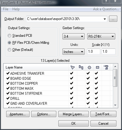
The main EasyGerb dialog.
![]()
(Screenshot of EasyGerb main dialog)

Output Folder.:
This setting determines which directory will be used to output the data from EasyGerb.
![]() Note: The Output Folder is defaulted to the current AutoCAD directory (Usually the current directory is the last opened drawing).
Note: The Output Folder is defaulted to the current AutoCAD directory (Usually the current directory is the last opened drawing).
![]() Note: The Output Folder should ALWAYS be set to a local directory on your computer, and not to a network location or other external device.
Note: The Output Folder should ALWAYS be set to a local directory on your computer, and not to a network location or other external device.
![]() Note: If you select a Output Folder that doesn't exist on your computer, EasyGerb will automatically create it for you.
Note: If you select a Output Folder that doesn't exist on your computer, EasyGerb will automatically create it for you.
Aperture File:
![]() Note: An aperture file is only needed if you select the Gerber Format: "RS-274D". For all other gerber formats the created Aperture List is only used as a reference and is not needed when sending out your gerbers to manucaturing or any other outside service.
Note: An aperture file is only needed if you select the Gerber Format: "RS-274D". For all other gerber formats the created Aperture List is only used as a reference and is not needed when sending out your gerbers to manucaturing or any other outside service.
Output Settings:
The "Output Settings" selection is a feature used to optimize your layer settings (such as FCB, OWP, PEC, FRD,FRS) for the most common type of design you're translating. Choose whatever description best describes the type of your design. The feature is optional.
Gerber Settings:
Export Gerber Format:
|
Select Gerber format to export. Either RS-274D, RS-274X or Fire9000.
|
Units:
|
Determine exported Gerber units of Inches or Metric. |
Integer Digits:
|
Determine exported Gerber integer digits between (0-6). |
Decimal Digits:
|
Determine exported Gerber integer digits between (0-6).
|
Scale X/Y:
|
Choose export scale in both X & Y direction. This feature is optional, and the default is 1 (ie. 1=1.0) |
![]() Note: To improve accuracy of exported Gerber files, select Decimal Digits of 4 (or higher) for example: 2.5, 3.4,etc.
Note: To improve accuracy of exported Gerber files, select Decimal Digits of 4 (or higher) for example: 2.5, 3.4,etc.
![]() Note: Gerber files exported from EasyGerb support polygon fills, composites, step/repeat, etc.
Note: Gerber files exported from EasyGerb support polygon fills, composites, step/repeat, etc.
![]() Note: Fire9000 has an additional resolution feature of 1/4 mil, 1/8 mil, or 1/16 mil. If you're exporting to Fire9000, you must choose the resolution from: Fire9000 (1/4), Fire9000 (1/8), Fire9000 (1/16)
Note: Fire9000 has an additional resolution feature of 1/4 mil, 1/8 mil, or 1/16 mil. If you're exporting to Fire9000, you must choose the resolution from: Fire9000 (1/4), Fire9000 (1/8), Fire9000 (1/16)
Layers Table:
Export:
|
If "checked" this layer will be exported to Gerber. If "unchecked", this layer will be omitted. |
Layer Name:
|
The AutoCAD layer name. This is merely for reference, and cannot be changed. |
If "checked", every closed & continous boundary for this layer will become filled polygons. If "unchecked", all closed boundaries for this layer will be open traces, and use the Default Line Width (for the Trace diameter). |
|
If "checked", it will create an outline for any polyline with width; essentially the polylines with width will appear exactly in gerber as they do in AutoCAD. If "unchecked", the centerline will be traced with a round dcode using the same diameter as the polyline width; commonly used for traces in PCB designs. |
|
If "checked", all Rectangles and Circles on this layer, which are smaller than the setting "Max. Flash Size (inch)", will be converted to Gerber Flashes. |
|
If "checked", all Rectangles and Squares on this layer, which are smaller than the setting "Max. Flash Size (inch)", will be converted to Gerber Flashes. |
|
If "checked", exports a NC Drill file for this layer. Only Gerber Flashes on this layer will be counted as drill hits. Make sure that you also check the adjacent option FRD for this layer. |
![]() Note: If a layer is turned "OFF" it will not be included in the EasyGerb layer table.
Note: If a layer is turned "OFF" it will not be included in the EasyGerb layer table.